
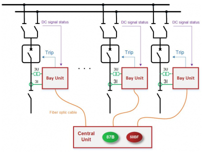
Functional block diagram of the OGYD protection
General presentation
Two different types of busbar differential protection are available: the OGYD protection and the DGYD protection. Essentially, both work on the well-known principle that the sum of the currents entering and leaving a busbar is equal to zero when there is no internal fault. If this sum is not equal to zero, it means that there is a fault on the busbar and a fast tripping command is generated. The scheme used in both versions is that of a low impedance biased differential circuit, based on the application of Kirchhoff’s current law.
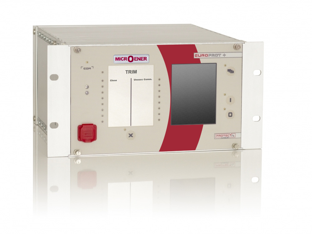
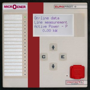
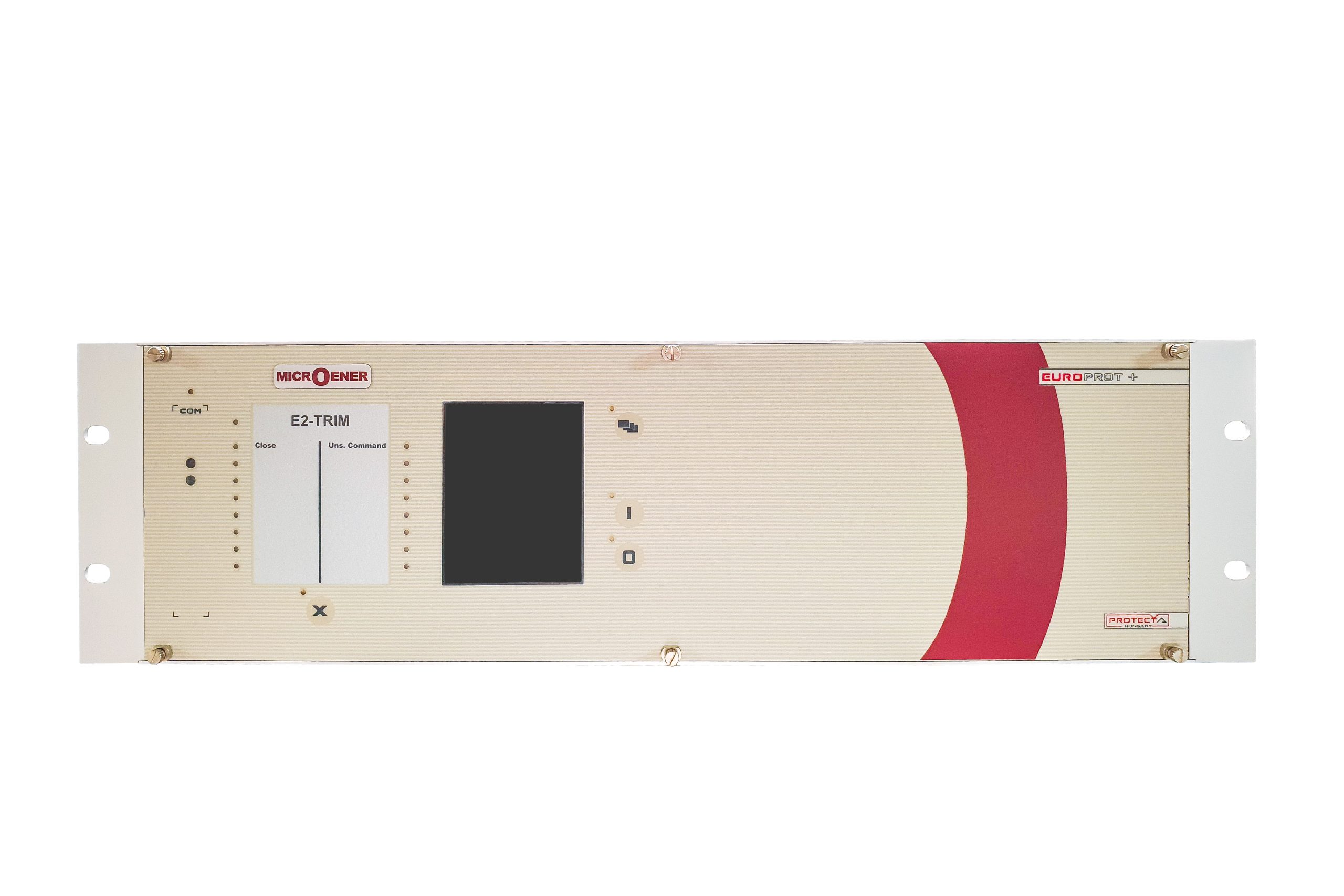
In the OGYD (decentralised) version, bay protection devices (distance protection, overcurrent protection, etc., or possibly dedicated bay units) are integrated into the busbar protection scheme as bay units. Their location in the substation depends on the bay structure of the transmission system. These devices sample the currents and have access to all the information required by the busbar protection system. This information is transmitted to the central unit over an optical fibre link. Calculation and decision-making are performed by the central unit, and the dedicated tripping commands are sent back to the devices, also over optical fibre links.
The EuroCAP configuration tool, available free of charge, provides a user-friendly and flexible application for protection, control and measurement functions, ensuring that the protection devices are fully customisable.
General features
- Native intelligent electronic device (IED) compliant with the IEC 61850 standard, Edition 2 compatible
- Scalable hardware adapting to different applications
- Rack width of 84TE or 42TE (height: 3U)
- The predefined factory configuration can be customised to the user’s specifications with the powerful EuroCAP tool
- Flexible protection and control functionalities to meet specific user requirements
- Advanced HMI functionalities via a colour touch screen and a built-in web server, extended measurement, control and monitoring functions
- User-configurable LCD displays, able to show single line diagrams (SLD) with switchgear position indication and control, as well as measurement values and several types of controllable objects.
- Various protection setting groups available
- Enhanced circuit breaker monitoring and control
- High-capacity disturbance recorder (DRE) and event logging (data stored in non-volatile memory):
- DRE supporting up to 32 analogue signal channels and 64 digital signal channels.
- The event recorder can store more than 10,000 events.
- Several mounting methods: rack-mounted; flush-mounted; semi-flush-mounted; wall-mounted; wall-mounted with terminals; flush-mounted with IP54-rated cover.
- Wide range of communication protocols
- Ethernet communication: IEC 61850; IEC 60870-5-104; DNP3.0 TCP; Modbus TCP
- Serial communication: DNP3.0; IEC 60870-5-101/103; MODBUS, SPA
- The PROTECTA range can handle several communication protocols simultaneously.
- Built-in self-monitoring function to detect internal hardware or software errors.
- Various time sources available: NTP server; minute pulse; legacy protocol master; IRIG-B000 or IRIG-B12X
Applications
The OGYD system is specially designed for use as the main unit of a decentralised low impedance protection system, to protect busbars with up to 30 bays.
Field of application
- The protection function is performed within a central module, but the analogue currents and the status signals coming from all the busbar bays are accessed by protection devices dedicated to each bay;
- The bay units can perform any other protection function, but they transmit logic information to the central module over optical fibre links;
- Dynamic busbar replica, based on the status signals of the disconnectors;
- High stability in the event of external faults, despite current transformer saturation;
- Short tripping time;
- Selectivity in the event of an internal fault: only the bays connected to the faulty busbar section are disconnected, all the other bays remain in service;
- Easy extension according to the busbar configuration;
- Easy adaptation of the function to different primary busbar systems:
- Single busbar,
- Up to quadruple busbar,
- Ring busbar,
- Breaker-and-a-half arrangement,
- Bus couplers,
- Busbar disconnectors with one or two current transformers,
- Transfer busbar;
- Individual digital calculation and decision-making for the three phases;
- Biased differential current characteristics;
- Increased security and stability thanks to special software features;
- Voltage failure condition,
- Check zone criteria implemented to increase stability,
- Compensation of saturated waveforms.
Protection and control functions
The differential and circuit breaker failure functions are dealt with together because the circuit breaker failure protection uses the status information processed by the busbar protection in order to disconnect only the busbar section to which the faulty circuit breaker is connected. The other zones therefore remain in service.
Click on the link to download the general documentation : Please contact our Sales Department
Technical sheet : NC_OGYD
Click on the link to download the operation manual : Please contact our Sales Department
Click on the link to access the technical documentation to attach to your order : DOCACOM_PROTECTA