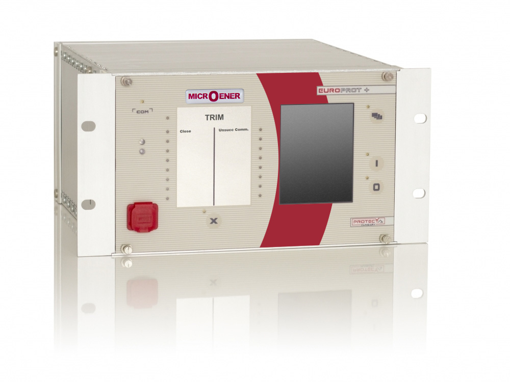

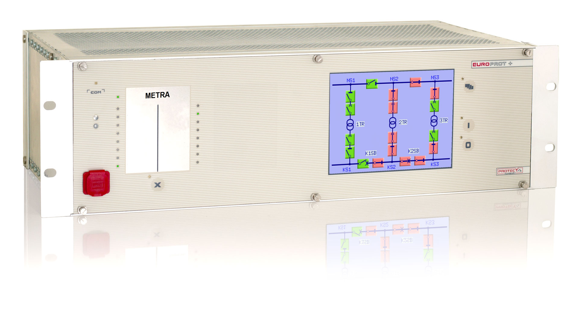
Source management with the METRA
General presentation
The factory configuration of the METRA system is designed to provide automatic transfer from an in-service supply transformer to a standby transformer feeding a busbar. The transfer is triggered by the tripping signals of the in-service transformer, received from other protection devices. Automatic transfer ensures that the back-up supply will not be energised in the event of a fault. To meet this requirement, the function checks whether the circuit breaker of the faulty transformer is in the “open” position; only then can the closing command be sent to the circuit breaker of the back-up supply. Closing the circuit breaker is only effective if the standby transformer is energised on the primary side. Before generating the closing command, this state is also checked. As a result, the transfer takes place with a very short dead time. During this period, no current is supplied to the busbar. The device can be implemented in transformer substations where the interruption time due to a loss of supply must be kept to a minimum.
The METRA system is an IED of the DAUT product family of the PROTECTA range. In hardware and software terms, this range is made up of modular devices. Because of this architecture, the modules are assembled and configured according to the user’s needs; from then on, the software determines the functions (SFB).
General features
- Native intelligent electronic device (IED) compliant with the IEC 61850 standard, Edition 2 compatible
- Scalable hardware adapting to different applications
- Rack width of 84TE or 42TE (height: 3U)
- The predefined factory configuration can be customised to the user’s specifications with the powerful EuroCAP tool
- Flexible protection and control functionalities to meet specific user requirements
- Advanced HMI functionalities via a colour touch screen and a built-in web server, extended measurement, control and monitoring functions
- User-configurable LCD displays, able to show single line diagrams (SLD) with switchgear position indication and control, as well as measurement values and several types of controllable objects.
- Various protection setting groups available
- Enhanced circuit breaker monitoring and control
- High-capacity disturbance recorder (DRE) and event logging (data stored in non-volatile memory):
- DRE supporting up to 32 analogue signal channels and 64 digital signal channels.
- The event recorder can store more than 10,000 events.
- Several mounting methods: rack-mounted; flush-mounted; semi-flush-mounted; wall-mounted; wall-mounted with terminals; flush-mounted with IP54-rated cover.
- Wide range of communication protocols
- Ethernet communication: IEC 61850; IEC 60870-5-104; DNP3.0 TCP; Modbus TCP
- Serial communication: DNP3.0; IEC 60870-5-101/103; MODBUS, SPA
- The PROTECTA range can handle several communication protocols simultaneously.
- Built-in self-monitoring function to detect internal hardware or software errors.
- Various time sources available: NTP server; minute pulse; legacy protocol master; IRIG-B000 or IRIG-B12X
Applications
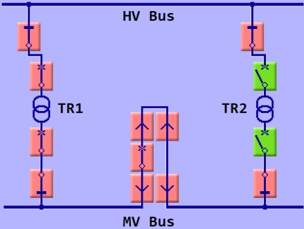
Based on the circuit breaker and disconnector positions indicated by the status signals, the METRA identifies the states of the substation. The permitted states are programmed according to the user’s requirements. In a permitted state, a tripping pulse initiates the transfer: the circuit breaker of the faulty transformer is opened, and that of the predefined back-up supply is closed. The back-up supply can be a standby transformer or a bus coupler in the busbar configuration. The diagram shown on the graphic LCD display indicates the actual positions (including intermediate or faulty states) of the switchgear.
Field of application
- The configuration is designed so that it can be adapted to several types of busbar systems with a minimum of modifications
- One single HV busbar, one single MV busbar with disconnector
- Two HV busbars, one single MV busbar with disconnector
- One single HV busbar, two MV busbars with disconnector
- Two HV busbars, two MV busbars with disconnector
- By default, the system supports one single busbar on each side and one disconnector on the MV side.
- Other types of schemes can also be created using the EuroCAP software.
Protection and control functions
The METRA device detects inconsistent substation states, when none of the predefined states can be identified from the switchgear status signals. In this case, the transfer function is disabled until a permitted state is reached.
Errors in the status signals also disable the transfer function. A time delay can be set for each circuit breaker and disconnector in order to report a status error. During the transfer procedure, the function keeps the initial state of the substation in order to avoid conflicting operating commands. During the transfer procedure, the function does not check the evolution of the substation state.
Click on the link to download the general documentation : Please contact our Sales Department
Click on the link to download the operation manual : Please contact our Sales Department
Click on the link to access the technical documentation to attach to your order : DOCACOM_PROTECTA